4.1.4.1. EM Data Type Functionality
4.1.4.1.1. Defining Transmitters
For FEM3Ddata, FEM3Dsounding, TEM3Ddata and TEM3Dsounding data objects, we can define transmitters for the survey.
This functionality is accessed using the drop-down menu:
“data type menu” → Add Transmitters
4.1.4.1.1.1. Add Transmitters to 1D sounding
Here, the user may specify the transmitter locations and properties based on the data locations.
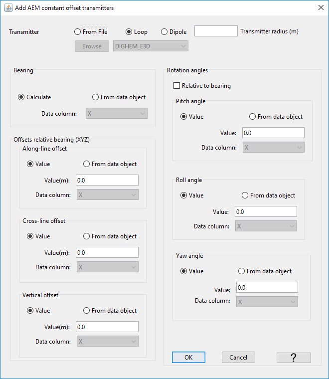
Select the object: “data type menu” → Add transmitters
- Transmitter geometry
From File: Lets the user import a template geometry (XYZ coordinates) defining the transmitter coil.
Loop: Defines a simple loop transmitter with radius set by the user.
Dipole: Defines a dipole transmitter with moment set by the user (for EM1Dinversion)
- Bearing
Calculate: Let GIFtools determine the bearing of survey lines. Assumes that the survey points are sorted in order of acquisition.
From data object: Bearing already supplied by the data object.
- Offsets relative to bearing (XYZ)
Along-line offset: Distance along the survey lines between the data location and transmitter
Cross-line offset: Distance perpendicular to the survey lines between the data location and transmitter
Vertical offset: Elevation difference between the data location and transmitter. For the EM1Dsounding class, the offset is relative to the ground.
- Rotation angles
Relative to bearing: Apply the rotation angles relative to the flight line orientation. Otherwise angles are relative to the Cartesian grid.
Pitch angle: Rotation angle about the wings of the bird. Positive angle moves the nose up, tail down.
Roll angle: Rotation angle about the length of the bird. Positive angle moves the left wing up, right wing down.
Yaw angle: Rotation angle about the XY plane. Positive angle rotates the bird clockwise.

Important
Make sure you have set i/o headers for the xyz-data locations. This functionality computes the transmitter locations based on the i/o headers.
4.1.4.1.1.2. Create Surface/Airborne Sources
Create inductive sources (loops) for surface or airborne EM surveys. This functionality is accessed using the drop-down menu:
“data type menu” → Add Transmitters → Create Surface/Airborne Sources
4.1.4.1.1.3. Create Single Inductive/Galvanic Source
Create a single inductive or galvanic source for all data in the object. This functionality is accessed using the drop-down menu:
“data type menu” → Add Transmitters → Create Single Inductive/Galvanic Source
4.1.4.1.2. Defining Receivers
For FEM3Dsounding and TEM3Dsounding data objects, we can define receivers for the survey.
This functionality is accessed using the drop-down menu:
“data type menu” → Add Receivers
4.1.4.1.2.1. Add Receivers to 1D sounding
4.1.4.1.2.2. Create Surface/Airborne Receivers
Create loop receivers for surface or airborne EM surveys. This functionality is accessed using the drop-down menu:
“data type menu” → Add Transmitters → Create Surface/Airborne Receivers
4.1.4.1.3. Remove Transmitters
This functionality allows the user to remove transmitter information from the data object.
Select the object and the menu “data type menu” → Remove transmitters
4.1.4.1.4. Remove Receivers
This functionality allows the user to remove receiver information from the data object.
Select the object and the menu “data type menu” → Remove receivers
4.1.4.1.5. Waveform (TDEM objects only)
Here, we describe functionality related to defining, viewing and exporting waveforms for TEM data objects. This functionality is accessed through:
data type menu → Waveform
4.1.4.1.5.1. Create Exponent On - Ramp Off
Here, the user defines an exponential ramp-on linear ramp-off waveform and sets it to the selected TEM data object. This functionality is accessed through:
data type menu → Waveform → Create exponent on; ramp off
The parameters defining this waveform are as follows:
minimum time: the starting time for the waveform (in seconds). This time must be before your first time channel
maximum time: the end time for the waveform (in seconds). This time must be after your latest time channel
time = 0: the shut-off time
Number of segments: Number of intervals after t0 which use a different time-step length
Samples per segment: Number of linearly sampled points which define the time-step length in each segment
Exponent slope: The constant \(\alpha\) defining the exponential ramp on
Exponent time: The duration of the exponential ramp on
Number of exp samples: Number of data points, linearly sampled, defining the waveform during the exponential ramp on
Ramp time: The duration of the linear ramp off
Number of ramp samples: Number of data points, linearly sampled, defining the waveform during the linear ramp off
4.1.4.1.5.2. Create Step Off
Here, the user defines a step-off waveform and sets it to the selected TEM data object. This functionality is accessed through:
data type menu → Waveform → Create step off
The parameters defining this waveform are as follows:
minimum time: the starting time for the waveform (in seconds). This time must be before your first time channel
maximum time: the end time for the waveform (in seconds). This time must be after your latest time channel
time = 0: the shut-off time
Number of segments: Number of intervals after t0 which use a different time-step length
Samples per segment: Number of linearly sampled points which define the time-step length in each segment
4.1.4.1.5.3. Import a Waveform
Here, the user imports a custom waveform from a text file and sets it to the selected TEM data object. This functionality is accessed through:
data type menu → Waveform → Import (3D format)
4.1.4.1.5.4. View
Here, the user may look at the waveform assigned to the selected TEM data object. This functionality is accessed through:
data type menu → Waveform → View
4.1.4.1.5.5. Export for 1D
Here, the user may export the waveform in the format used by the EM1DTM code. This functionality is accessed through:
data type menu → Waveform → Export for 1D
4.1.4.1.5.6. Export for 3D
Here, the user may export the waveform in the format used by 3D codes. This functionality is accessed through:
data type menu → Waveform → Export for 3D