10.2.7. OcTree Mesh Design
Here we provide a basic approach for mesh design when inverting DC/IP data. Mesh design for DC/IP problems depend on both the maximum and minimum electrode spacing. We explain how to create an OcTree mesh based on DC/IP survey geometry. We also explain the reasoning for the parameter values entered for the tutorial data. We can create OcTree meshes from DC/IP surveys with the following utility:
Once you have created the object, complete the following steps:
Set the data object corresponding to the survey
Define the mesh using Edit Options
Run the utility
Load results. The files loaded will include a data file data_Z.txt wherein the surface electrodes have been projected to the discrete surface topograpy.
For the tutorial data, the parameters set in Edit Options are shown below. For definitions of the parameters, consult the DCIP octree manual .
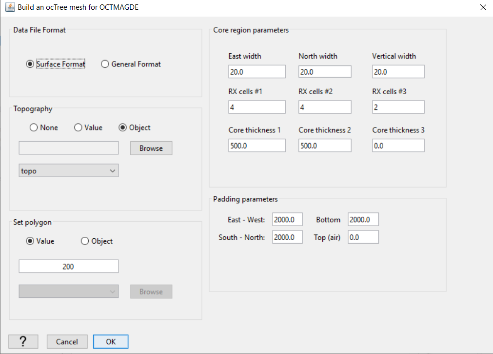
Parameters used to define the mesh for the field dataset using DCIP OcTree mesh utility.
10.2.7.1. Comments on Choosing Parameters
File format: Since all electrodes are located on the Earth’s surface (i.e. no borehole), we use the surface option to project all electrodes to the disrete surface topograpy. If we had borehole data, we would use the general file format option.
Minimum cell size: The minimum cell size is determined by the minimum electrode spacing. To have sufficient accuracy, you must have at least 2.5 to 4 cells between each electrode.
Core region discretization: Thickness 1 should be used to discretize the region with the largest currents. For dipole-dipole data, this should be 30% to 50% the size of the largest electrode spacing. For pole-dipole or dipole-pole data, this should 75% to 100% the size of the largest electrode spacing. If you let Thickness 1 be on the smaller side, make sure Thickness 2 is equal or greater than Thickness 1.
Padding cell expansion: The extent of the mesh depends on the largest electrode spacing. The thickness of the padding should be about 2-3 times the length of the largest electrode spacing.
Number of cells around Rx: The number of fine mesh cells near receivers must be sufficiently large to model the electric potentials near electrodes accurately. It is important to set RX cells #1 to be between 4 and 8.
Make polygon: This parameter controls the horizontal extent of the core mesh region. In practice, the distance between any electrode and the horizontal edges of the core mesh region should be 2-3 times larger than the smallest electrode spacing.