5.1.6. DC/IP 2D Locations file
This file contains the electrode locations for DCIPF2D. The electrodes file follows the same formats at the Observations files, but without data and standard deviations. Thus, an electrode file can have three different formats: the general, surface, or simple format. Only a single format is allowed in a data file. The general format is the only format that will allow the use of borehole locations. The type of format chosen for forward modelling does not make any difference to the DCIPF2D and is determined only by the user’s preference. At the beginning of execution, the programs will determine the format and the output files will be written in the same format.
5.1.6.1. General format
The forward modelling code DCIPF2D can handle arbitrary electrode configurations, and a mixture of different configurations can be present in the data file. This is accomplished by specifying the locations of four electrodes for each location. Whenever the two current electrodes, or two potential electrodes, are given the identical location, that particular pair is considered to be a single pole with the negative electrode being at infinity. The format consists of a line with the current electrode location and number of potential electrode locations associated with it. Each location has \(x\) and \(z\) coordinates. An example of the format file structure is as follows:
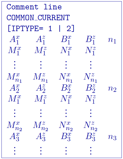
\(\text{COMMON_CURRENT}\): This flag is given prior to to let the code know that it is a general format file
\(Comment~line\): Any comments can go here. This line is ignored by and must have a preceding “!”
\(\text{'number of sources'}\): integer number giving the totla number of sources in the file.
\(IPTYPE\): Only used for IP inversion and not required if only using DC inversion. NOTE: If omitted from IP inversion, the program will choose \(IPTYPE=1\).
\(IPTYPE=1\), Type of IP data is apparent chargeability
\(IPTYPE=2\), Type of IP data is secondary potentials
\(A^x_i\): i\(^{th}\) horizontal position along line of current electrode A
\(A^z_i\): i\(^{th}\) elevation of current electrode A
\(B^x_i\): i\(^{th}\) horizontal position along line of current electrode B
\(B^z_i\): i\(^{th}\) elevation of current electrode B
\(M^x_j\): j\(^{th}\) horizontal position along line of potential electrode M associated with the i\(^{th}\) current pair
\(M^z_j\): j\(^{th}\) elevation of potential electrode M associated with the i\(^{th}\) current pair
\(N^x_j\): j\(^{th}\) horizontal position along line of potential electrode N associated with the i\(^{th}\) current pair
\(N^z_j\): j\(^{th}\) elevation of potential electrode N associated with the i\(^{th}\) current pair
5.1.6.1.1. Example of general format
The following is an example of locations for DC data (e.g., no IPTYPE):
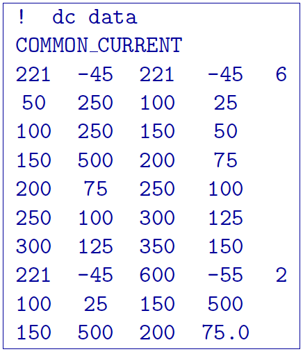
In the above example, there are two current electrode locations, the first with six potential electrodes and the second with two potential electrode data. The line “IPTYPE=2” would be added if this file were IP data of second potentials.
5.1.6.2. Surface format
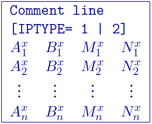
The surface format is similar to the general format with difference that the elevation data is not given. Instead, the program places the electrodes on top of the discretized topographic surface. Accordingly, this format cannot be used with borehole data and if no topography is given, assumes the data are on top of the mesh at an elevation of 0. Whenever the two current electrodes, or two potential electrodes, are given the identical location, that particular pair is considered to be a single pole with the negative electrode being at infinity. The format consists of a line with the current electrode location and number of potential electrode locations associated with it. An example of the format file structure is as follows:
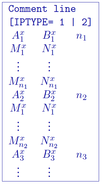
The following are detailed summaries of components of the surface-format observations file:
\(Comment~line\): Any comments can go here. This line is ignored by dcipf2d and must have a preceding “!”
\(\text{'number of sources'}\): integer number giving the totla number of sources in the file.
\(IPTYPE\): Only used for IP inversion and not required if only using DC inversion. NOTE: If omitted from IP inversion, the program will choose \(IPTYPE=1\).
\(IPTYPE=1\), Type of IP data is apparent chargeability
\(IPTYPE=2\), Type of IP data is secondary potentials
\(A^x_i\): i\(^{th}\) horizontal position along line of current electrode A
\(B^x_i\): i\(^{th}\) horizontal position along line of current electrode B
\(M^x_j\): j\(^{th}\) horizontal position along line of potential electrode M associated with the i\(^{th}\) current pair
\(N^x_j\): j\(^{th}\) horizontal position along line of potential electrode N associated with the i\(^{th}\) current pair
5.1.6.2.1. Example of surface format
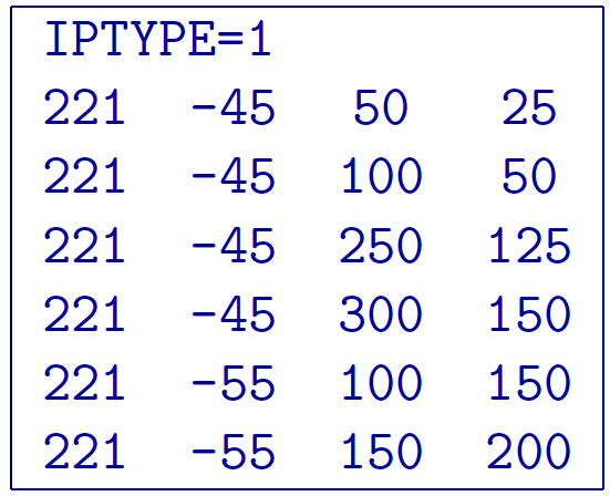
The following is an example of IP data in units of apparent chargeability:
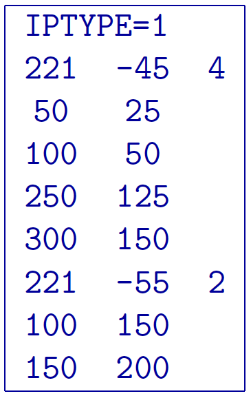
In the above example, there are two current electrode locations, the first with four potential electrodes and the second with two potential electrode data. The line “IPTYPE=1” would be absent if this file were DC data.
5.1.6.3. Simple format
The simple format is the most straightforward, but also most restrictive of the three formats. The elevations are not given similar to the surface format with difference that the elevation data is not given. Instead, the program places the electrodes on top of the discretized topographic surface. Accordingly, this format cannot be used with borehole data and if no topography is given, assumes the locations are on top of the mesh at an elevation of 0. Whenever the two current electrodes, or two potential electrodes, are given the identical location, that particular pair is considered to be a single pole with the negative electrode being at infinity. The format consists of a line with the current electrode pair location and potential electrode location pair. An example of the format file structure is as follows:
The following are detailed summaries of components of the simple-format observations file:
\(Comment~line\): Any comments can go here. This line is ignored by dcipf2d and must have a preceding “!”
\(IPTYPE\): Only used for IP inversion and not required if only using DC inversion. NOTE: If omitted from IP inversion, the program will choose \(IPTYPE=1\).
\(IPTYPE=1\), Type of IP data is apparent chargeability
\(IPTYPE=2\), Type of IP data is secondary potentials
\(A^x_i\): i\(^{th}\) horizontal position along line of current electrode A
\(B^x_i\): i\(^{th}\) horizontal position along line of current electrode B
\(M^x_j\): j\(^{th}\) horizontal position along line of potential electrode M associated with the i\(^{th}\) current pair
\(N^x_j\): j\(^{th}\) horizontal position along line of potential electrode N associated with the i\(^{th}\) current pair
5.1.6.3.1. Example of simple format
The following is an example of the simple format. The data are the same as given in the surface format example; IP data in units of apparent chargeability: