9.5.1. Survey Design and Forward Simulation
Here, we show how to create a simple dipole-dipole DC Resistivity survey over a conductivity model and run the forward simulation.
9.5.1.1. Setup for the Exercise
Open GIFtools
Tip
Requires at least
GIFtools 2.26(login required)
9.5.1.1.1. Create Overlapping surveys
In order to compare the resolving capabilities of different survey configurations, we will generate two sets of line data with the following specifications:
Use the DCIP Survey Designer
Block 1 |
Block 2 |
|
Survey Type |
DC |
DC |
Transmitters/Receivers |
pole-dipole |
pole-dipole |
IP Type |
Apparent Chargeability |
Apparent Chargeability |
Dimension |
3D |
3D |
Centroid |
557250 E, 7134000 N |
557400 E, 7133600 N |
Bearing |
\(45^\circ\) |
\(90^\circ\) |
Line Length (m) |
1500 |
1500 |
Line Spacing (m) |
300 |
100 |
Nb. lines |
5 |
5 |
Electrode Spacing (m) |
60 |
60 |
Nb. Receivers |
20 |
20 |
Note
The survey do not contain elevation information. We will let the code set the vertical position based on the discretized topography.
9.5.1.1.2. Merge the surveys
- Since we are creating two separate surveys, the
lineIDassigned to Block 1 and 2 will be repeated. We will add a constant to the line ID so that they are all unique identifiers. Add constant value to Block 2
lineIDproperty (+ 5)
- Since we are creating two separate surveys, the
- Select Block 1 and combine block 2 to form one large survey.
Data Manipulation → Add Data → Merge other DCIP3D data
Rename the combine object
DCSurveyFull
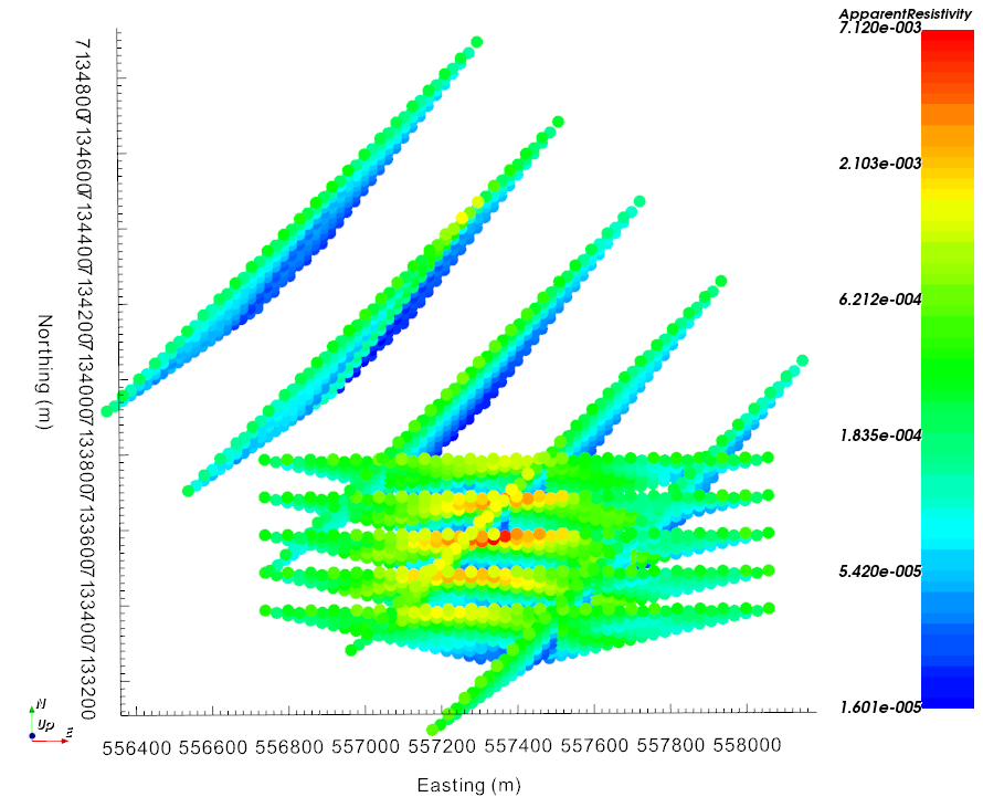
9.5.1.1.3. Forward model DC data
Create a DC Forward object
- Edit input options
Set
LocationstoDCSurveyFullSet
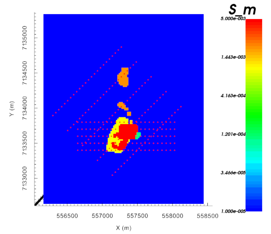
TopographytoTOPOdataand selectTKCtopoSet
ConductivitytoTKC_condModel
- Write files
Select
Surface Data Format
After completion, Load the predicted data
9.5.1.1.4. Forward model IP data
Create a IP Forward object
- Edit input options
Set
LocationstoDCSurveyFullSet
TopographytoTOPOdataand selectTKCtopoSet
ConductivitytoTKC_condModel
- Write files
Select
Surface Data Format
After completion, Load the predicted data