9.4.1. Specifying Parameters for TEM Sounding Inversion
Here, we detail the process of defining the survey parameters used in EM1DTM inversions. For GIF formatted 1D TEM data, the survey parameters are automatically read into GIFtools. For Geosoft XYZ and CSV files however, the survey information must be specified by the user. In this exercise, we:
Define the data columns being imported from a column data file
Set transmitter, receiver and elevation information
Assign uncertainties to the data
9.4.1.1. Setup for the Exercise
Open GIFtools
Attention
Requires at least
GIFtools version 2.26(login required)
9.4.1.2. Import files
We will begin by importing all the necessary information:
Import raw TEM data from the file
TKCdata_VTEM.xyz. Import data as Time-Domain EM → XYZ → TEM sounding (recipe)
Under channel information, import the time channels from the file
VTEMtimes.dat. Only 1 data groups so this does not need to be specified.When specifying headers, choose load file and use
VTEMheader.txt. Don’t forget to specify header name.Set IO header for the data column as the newly created dB/dt column
Import topography data from the file
TKCtopo.dat(3D GIF format)Import 1D mesh from the file
layer.msh(layers file)
Tip
Use Edit → Rename to change what objects in GIFtools are called
For any data object, edit the data headers.
Raw data were generated synthetically using the best-available conductivity model for TKC and the TDoctree code.
9.4.1.3. Set Survey Information
Since the raw data were formatted in CSV format, the transmitter and receiver information for the airborne survey must be set manually. Additionally, only an altitude column was provided in the raw data. Therefore, we must use the topography and altitude information to determine the elevation of each data point.
Create elevation from surface topography
From the
TKCdata_VTEMdata object use theraltdata column to shift the location vertically.Set i/o header for Z to the elevation column you just created
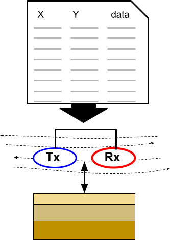
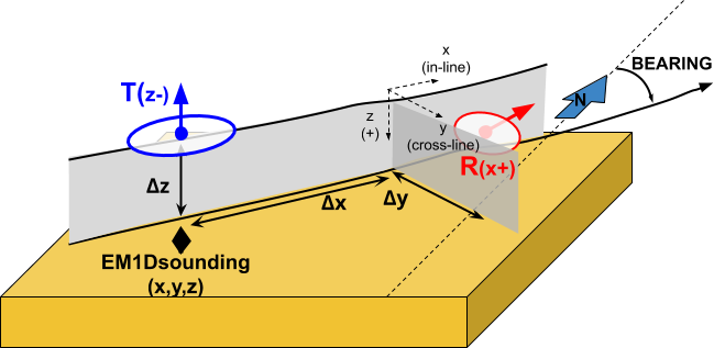
Add transmitters to set the locations of the transmitters relative to the current xyz data locations. For the coincident loop system used for the survey we set the following parameters:
Loop transmitter with radius of 10 m
Along-line offset = 0 m
Cross-line offset = 0 m
Set vertical offset as altitude column (
ralt) from TEMsounding objectAdd receivers to set the locations of the receivers relative to the transmitter locations. Use the following parameters:
Dipole moment = 1 Am \(\! ^2\)
Along-line offset = 0 m
Cross-line offset = 0 m
Set vertical offset as altitude column (
ralt) from data objectSet data normalization to Volts. This determines the data units written to the observations file and interpreted by the EM1DTM code.
Import and set waveform using the file VTEM.wave (3D format)
Important
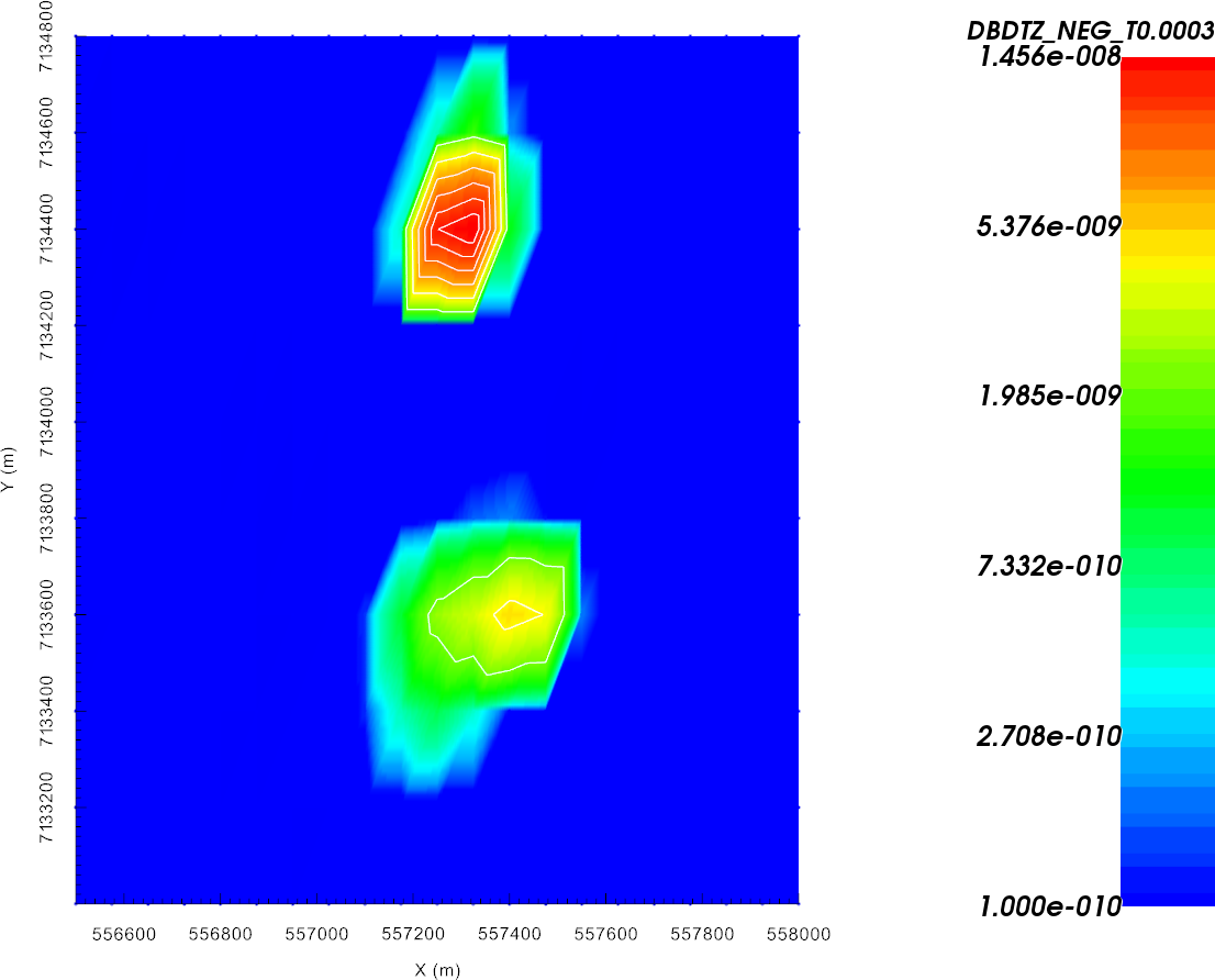
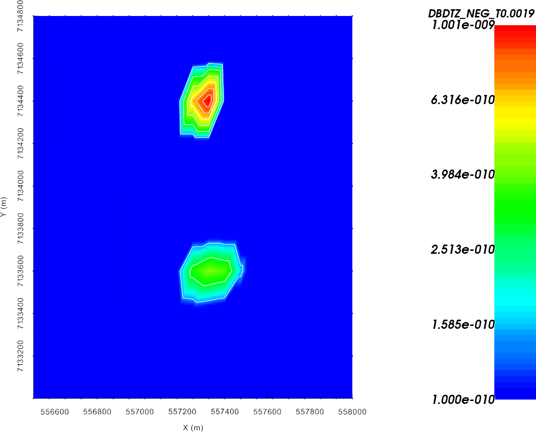
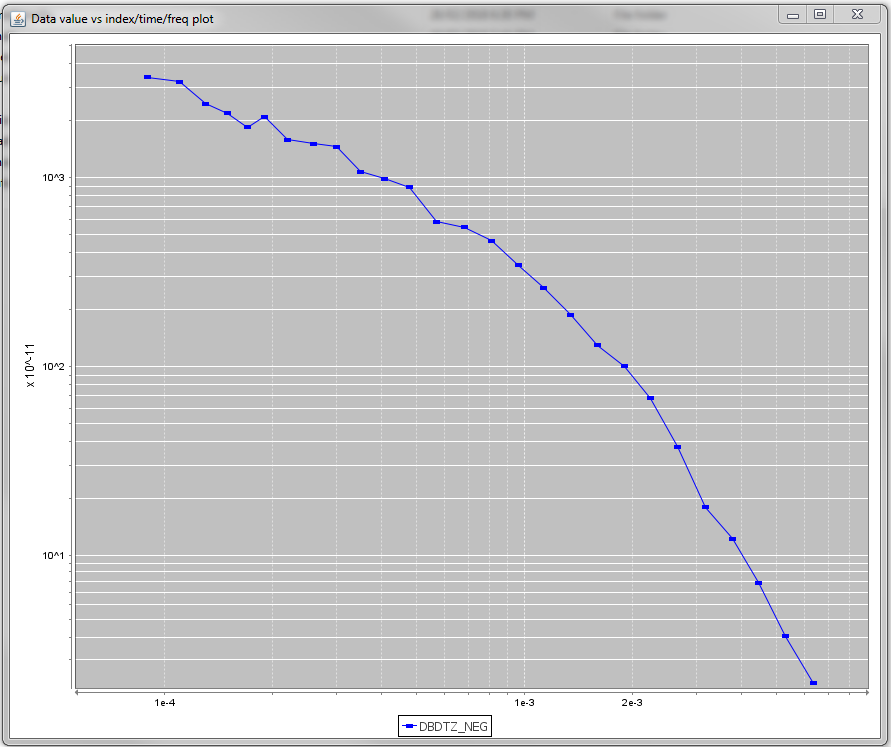
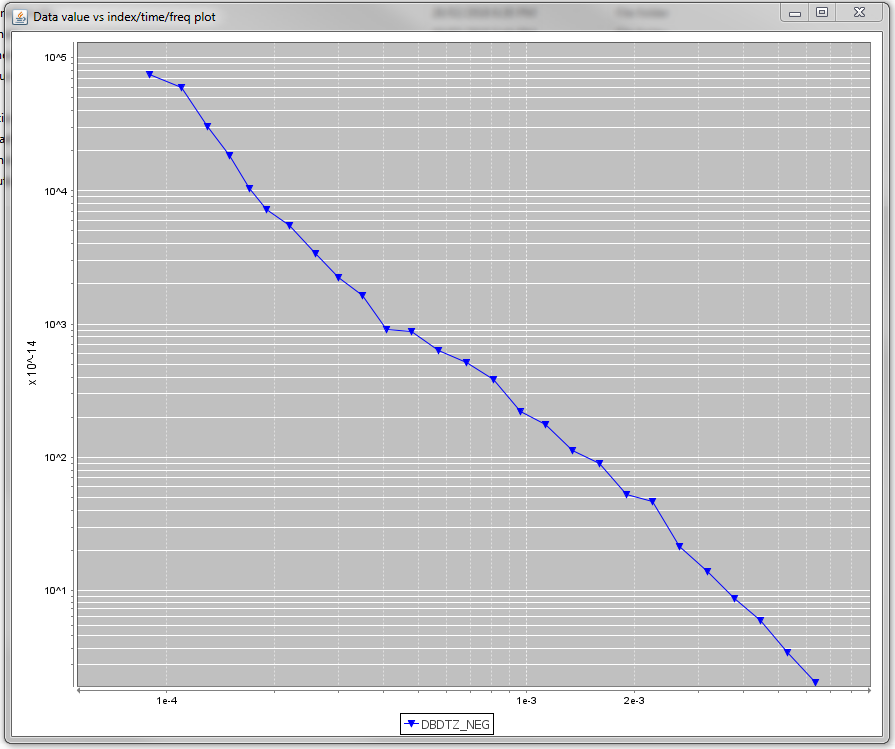
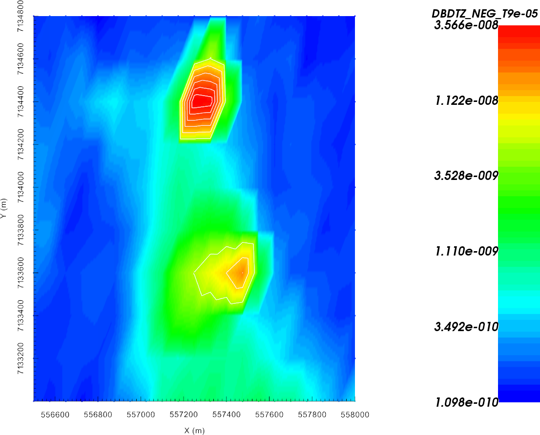
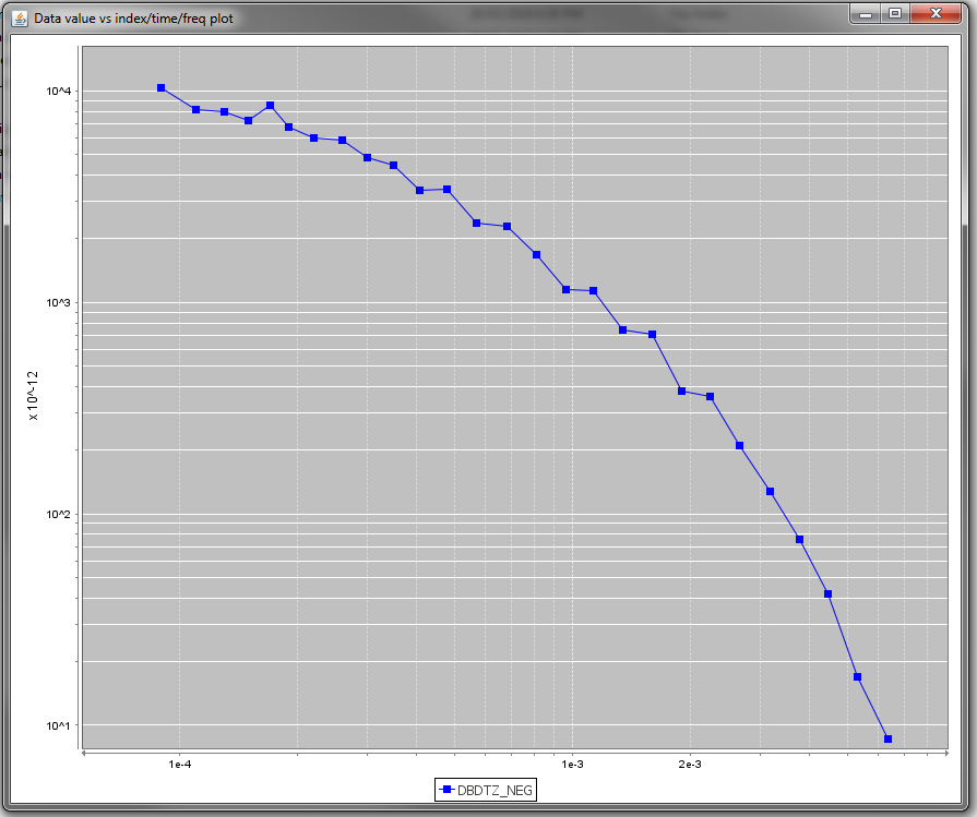
In keeping with a commonly used convention, we have chosen to plot -dBz/dt to show a positive decaying response; thus dBz/dt for a coincident loop system is negative and decaying in the universal coordinate system used by GIFtools. When loading TEM which are not already in GIF format, it is important that the sign of the vertical response is correct.
 |
 |
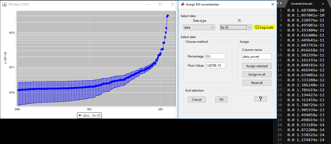
9.4.1.4. Assign Uncertainties
Before inverting the data, we must assign uncertainties. The role of uncertainties in the inversion process is described in the inversion fundamentals section. Because the observed response spans multiple orders of magnitudes of all time channels, and the errors on the data may vary as such, distinct floor and percent uncertainties will be computed for each time channel.
Assign uncertainties from file
Uncertainties.dataYou can review the uncertainty with the GUI to verify your work.
Note
The uncertainties for this exercise are based on the response over the gackground model so that the recovered model will not fit the dat too heavily in certain regions at the expense of others