3.3.1.9.1. Import FEM data
To import frequency-domain electromagnetic (FEM) data, use the main project menu:
Import → Data → Frequency-domain EM
There are four types of FEM data that can be loaded from files:

File formats:
3.3.1.9.1.1. EM1DFM format
Loads a data file for the EM1DFM inversion and forward modeling codes. The data position is set relative to the transmitter as specified by the EM1DFM file format. The function returns a FEM1Dsounding object.
Import → Data → Frequency-domain EM → GIF EM1D format
The following parameters are set for the user:
Properties:
- Receiver:
Dipole moment: mom_r
Along-line offset: The along-line position of receivers, relative to transmitter locations
Cross-line offset: The cross-line position of receivers, relative to transmitter locations
Vertical offset: Relative to topography
Note
The position of the data is set by the “sounding” location. Only the relative offsets between the transmitters and receivers are available in the EM1DFM file format. Data locations have been assigned to the transmitter locations upon import for consistency.
3.3.1.9.1.2. E3D format
Loads data files formated for the original E3D data file format . The function returns an FEMdata object where only the transmitter geometry is defined. The receivers are defined as point measurements that samples the fields (E, H) along the Cartesian axes.
Import → Data → Frequency-domain EM → GIF E3D format
Note
The FEMdata object assumes that the provided field data have been measured along the Cartesian axes or that the user has rotated the fields in pre-processing. For more general cases with arbitrary receivers orientation (in-line), consider making use of the FEM3Dsounding class.
3.3.1.9.1.3. E3D v2 format
Loads data specifically formatted for the E3D v2 and E3D v2 tiled codes. The function returns an FEM3Dsounding object.
Import → Data → Frequency-domain EM → GIF E3D v2 format
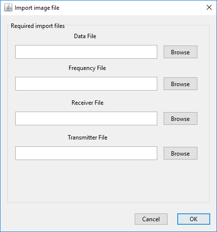
The receivers and transmitters are defined by their respective input files. As a result, you will need 4 files when importing E3D v2 data:
Note
Both the transmitters and receivers geometry are defined in 3D. The relative offsets can be calculated using the Calculate Transmitter/Receiver separation function.